Engineers in most industries require accurate methods to assess compressive force, whether during the development of a product or as an embedded component within a device or product.
Machines must regulate and measure the forces that they apply to the objects they come into contact with in industrial automation. Medical devices and human-machine-interfaces (HMIs) must analyze force as well, although on a much smaller and more accurate scale.
Regardless of the application, engineers frequently deliberate about the ideal method for analyzing force feedback in their applications. They must take upfront and operating costs, precision, form factor, power requirements, and other factors into account.
In a wider sense, force sensitive resistors (commonly called FSRs) and load cells are the two most commonly used methods. Force sensitive resistors can be further reduced into shunt mode and thru mode categories. Read this article to discover the differences between these force measurement methods.
Design and Operation
When connected to the appropriate electronics, load cells are transducers that return a signal in proportion to the mechanical force applied to the system. They can be pneumatic, hydraulic, or are based most frequently on strain gages.
The most commonly used strain gages are sensors created from an insulating base material with a metallic foil mounted to it. When the strain gage is fixed to an object, as the object deforms, the metallic foil also deforms, making the electrical resistance change.
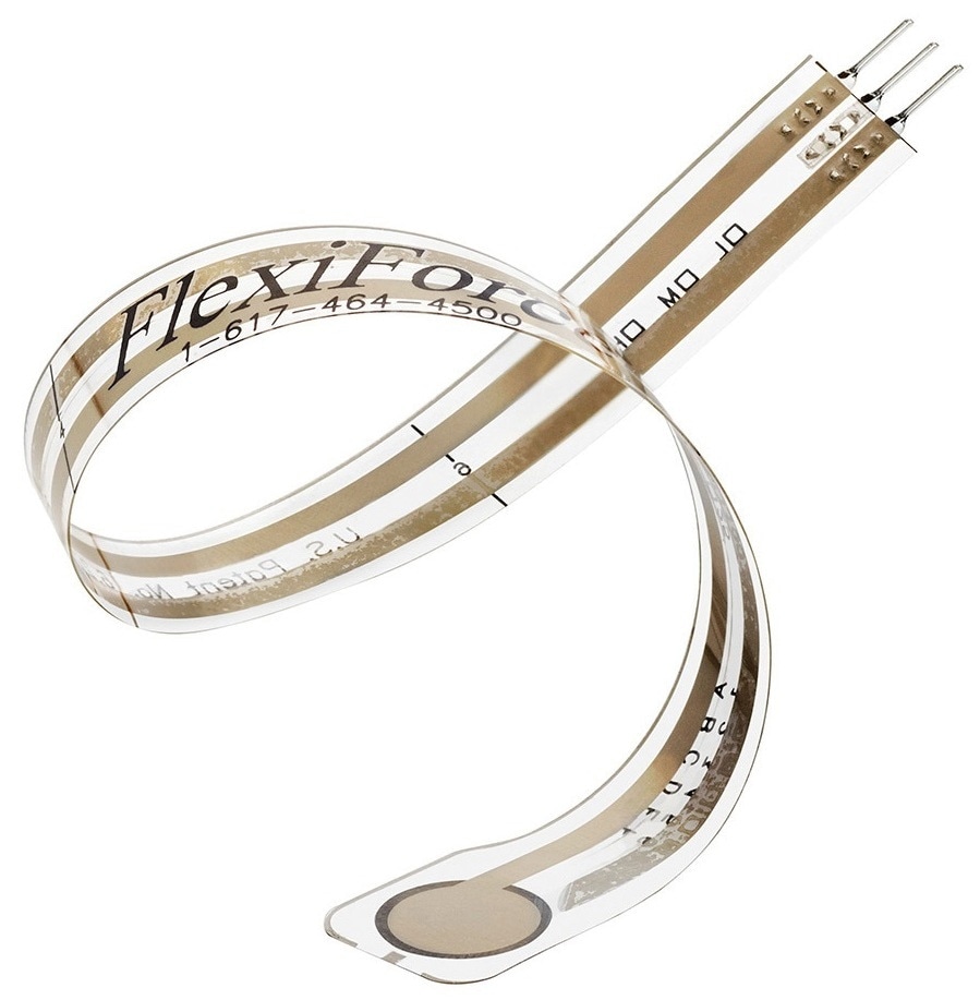
Example of a thru mode force sensitive resistor
The resistance change is relative to the strain by the strain gage’s gage factor. Strain gage load cells commonly utilize a double- or single-ended beam setup and between one to four strain gages. The beam can be attached on one end and loaded on the free end, or can be attached on both ends and loaded in the center.
In either setup, loading deforms the metal beam and creates a slight strain in the gages bonded to the beam surface. The strain makes a very slight change in the electrical resistance of the gages, which associated electronics commonly translate to a millivolt signal.
Greater loads result in greater strain and a proportional rise in the resulting signal. A different way to give embedded force feedback is with the use of force sensitive resistors. Force sensitive resistors change resistance when force is applied directly to them, whereas strain gages are planar resistors that change resistance in response to surface deformation.
The particular design of a force sensitive resistor is dependant on its mode of operation: thru mode or shunt mode. Shunt-mode force sensitive resistors comprise of two thick-film polymer layers.
One layer has interdigitated conductive traces while the other consists of force sensitive material. The force sensitive material shorts out the traces as force is applied, making the resistance decrease as the applied force becomes greater.
Thru-mode force sensitive resistors also comprise of two layers, both thin-film polymers with traces. Each polymer layer holds a semiconductive pressure sensitive element printed on a conductor.
The two layers are combined together. In the condition that is unloaded, the sensor’s resistance is extremely high (frequently MΩ). When force is applied, the pressure sensitive elements within the sensor contact each other and deform elastically.
The resistance of the sensor decreases (typically kΩ) as more force is applied. Inversely, the conductance of the sensor becomes greater as applied force increases. The relationship between the applied force and conductance for a thru-mode sensor is linear. This will be outlined in greater detail in the next section.
Performance
For an engineer looking for force feedback from an application, of similar or greater importance than how it works is how effectively it works. As such, it is vitally important to measure precision and accuracy, linearity, and dynamic range.
Load cells are reputed for their high precision, which had resulted in them becoming staples in test-and-measurement applications. Load cells which are well calibrated are precise to within 0.1% or less of their total scale.
Force sensitive resistors perform well in relative measurements, such as when detecting progressive changes in load for example those required for force feedback in human-machine and medical interface applications.
They are not as precise in absolute measurement, with well-calibrated shunt-mode force sensitive resistors performing average errors from 4 to 6% of absolute, and thru-mode force sensitive resistors coming in at around 5 to 10% of absolute (according to the quality of the calibration).
Force vs. Resistance & Force vs. Conductance of Common Touch Sensor Technology
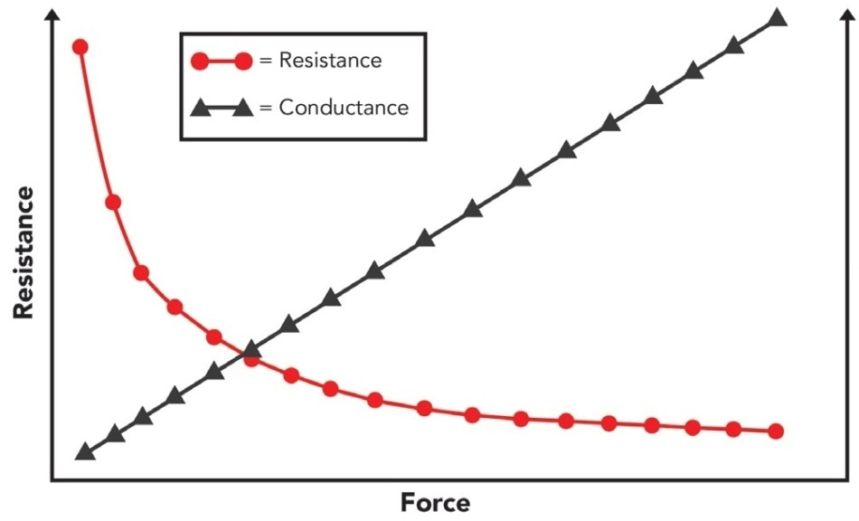
This graph demonstrates the results of force applied to a thru mode sensor. With higher applied force, the sensor’s resistance falls and creates a linear conductance signal.
Linearity is a term for how closely a force measurement sensor’s output adheres to a straight line drawn between the minimum and maximum loads or other points of calibration.
A sensor with low linearity error, normally expressed as a percentage of full scale, is much easier to calibrate. Engineers can be safe in the knowledge that the readings between calibration points are precise and that the slope of the sensor’s conductance curve is consistent through its designated force range.
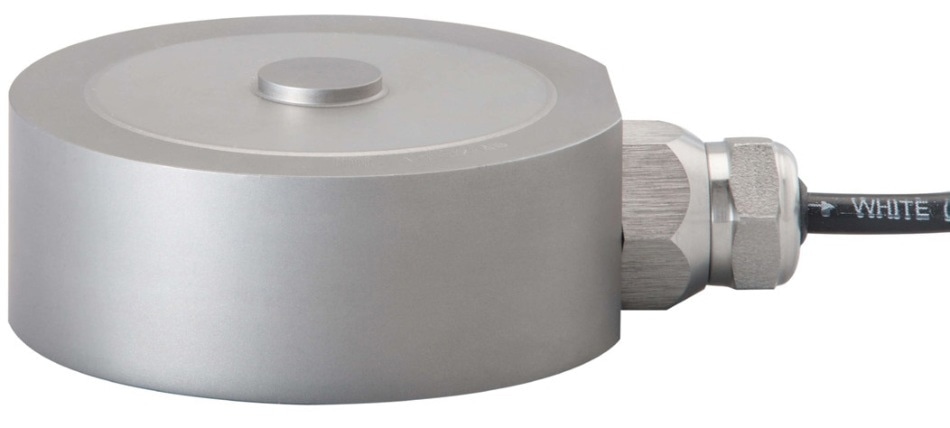
Image courtesy of Flintec
It is therefore beneficial that less intermediate calibration points are required. The force sensor’s design can impact its linearity at different loads. As an example, load cells provide nonlinearity at the lower portion of their load range. This makes them more appropriate for higher loads, but also reduces their useful range.
Engineers utilizing load cells should ensure that surplus load capability is limited and must shield the load cells from partial overloading, along with being sure to keep loads higher than the lowest calibration point. Thru-mode resistors are linear from 0 N to the top of their range and provide nonlinearities of ±3% of full scale throughout.
Even within their designated force range, shunt-mode force sensitive resistors are prone to deviate from linear behavior. Users of shunt-mode force sensitive resistors must utilize more calibration points than they would with thru-mode sensors. The range of measurable loads is another factor to consider for force measurement methods.
The majority of engineers are more concerned with dynamic range, which is the most possible range of force values that the sensor will see during its application. Load cells can be produced for a large variety of dynamic ranges, with the lower end identifying loads of 0.5 N or less and the upper end reaching into the tens of thousands of Newtons.
In contrast, force sensitive resistors are created to precisely analyze smaller force amounts. Shunt-mode force sensitive resistors are created for forces between 0.2 and 20 N. Thru-mode force sensitive resistors can be customized to maintain and assess linearity through various dynamic ranges of between 0.002 Pa and 69 MPa (10,000 psi).
Certain force sensors can drift in time so that the electrical signal is returned by the sensor changes, even though there is a constant load. Drift can be made more pronounced by environmental effects such as differences in humidity or temperature.
For instance, load cells can drift when temperature differences create the contraction or expansion of the surface where the strain gages are mounted, particularly if they are not placed in a self-correcting Wheatstone bridge configuration.
The standard drift is 5% per log (time) for shunt-mode force sensitive resistors. Thru-mode force sensitive resistors are rated <5% per log time. Drift rates can vary according to the material interface in both shunt and thru-mode force sensitive resistors.
Electronics and Maintenance
One element of selecting the correct force measurement sensor for an application is the consideration of the infrastructure that comes with that sensor. Every type of sensor needs integrating into a measurement circuit to ensure that an analog signal proportional to the applied force can be generated.
There are also requirements for maintenance and power to consider. The signal and power processing needs are varied according to the type of force measurement sensor. Load cells need a conditioned power source supplying the expected voltage by the sensor, normally 10 VDC or less.
They also require a dedicated digital signal processing (DSP) setup which allows for highly accurate force measurement, but adds cost and complexity to the setup and makes it more challenging to integrate into an application that is streamlined. Both thru-mode and shunt-mode force sensitive resistors have a basic relationship between conductance (1/ Resistance) and force.
This makes the determination of force from the sensor output simpler. As they are more frequently employed for relative force measurements, no extra provisions must be made for supplying power. Force sensitive resistors can normally be powered through an easy op-amp circuit or a voltage divider.
According to the application, the resolution of the force sensitive resistors and the force measurement range can be adjusted by changing the resistance of the feedback resistor and the drive voltage. Any person who has utilized a load cell understands that it is critical to maintain calibration.
Calibrated with the highest precision by the manufacturer, load cells may need to be sent off periodically for recalibration, or in the event of adverse events such as overheating or shock loading. Force sensitive resistors are user-calibrated, which, while convenient, can additionally introduce the possibility of user error.
Design Considerations
A key consideration in selecting a force measurement sensor is how easily it will fit into the pre-existing design or laboratory setup. Form sizes and factors have a critical role in how simple it is to integrate the sensor into a product.
Maintenance and cost are two other factors to consider in the integration decision. Load cells normally have a fixed, three dimensional shape and tend to be heavier. Designers aiming to integrate load cells into a product normally need to build elements of the design around the sensor, which makes it difficult to efficiently iterate the design.
Load cells’ DSP requirements, power, and their greater price have made load cells difficult to integrate into modern streamlined designs. Alternatively, both shunt-mode and thru-mode force sensitive resistors are flexible and flat.
Force sensitive resistors are much simpler to integrate into robotics, machines, and human-machine interfaces, along with the fact that they can be powered using simple electronics. Force sensitive resistors are also cheaper and need less infrastructure, so designers can more conveniently discover how best to integrate them into a design.

This information has been sourced, reviewed and adapted from materials provided by Tekscan, Inc.
For more information on this source, please visit Tekscan, Inc.