The key design function and purpose of circuit breakers is to be able to ‘trip’ when exposed to currents beyond their rated levels. When managing power protection requirements across various applications, sometimes high-inrush currents generate the potential for nuisance tripping if the circuit protection is poorly designed.
A maximum pulse, around 4 milliseconds in duration, can occur when switch closure corresponds with the supply's peak voltage point and the load has low initial impedance, such as a high capacitive load, an incandescent lamp bank, or a ferroresonant transformer. Nuisance trips will occur if pulse energy exceeds the energy required to trip the protector.
The initial amplitude of surges in a tungsten lamp may be around 15 times more than the rated steady-state current – the subsequent cycles are much lower. While increasing the protector inrush rating is feasible, it is only possible at the expense of overload protection.
In another example, capacitive input filter charging is similar to an RC charge curve. At its peak, the current is limited by charge circuit resistance and the power supply. Here, surges are less burdensome; transient duration is extremely short.
Transformer inrush is the most frequently encountered application problem. Its waveform is akin to that of a lamp-load inrush. However, contrary to a lamp-load inrush, the transient will not come to pass at each turn-on. However, similar to the lamp load, it has a maximum peak value when closing the circuit near the supply wave’s maximum voltage. Design trends necessitate reducing the size and weight of system components, especially transformers. Contemporary transformers with grain-oriented, high-silicon steel cores demonstrate significant “very high inrush current at turn-on” problems.
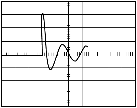
Figure 1. Example Tungsten Lamp Load Transient. Image Credit: Sensata Technologies, Inc.
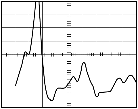
Figure 2. Transient from capacitive filter. Image Credit: Sensata Technologies, Inc.
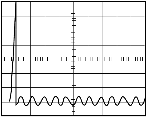
Figure 3. Transformer starting transient. Image Credit: Sensata Technologies, Inc.
These currents can be up to 30 times the standard rated current, compared to approximately older transformers, around 18 times the standard. The greatest “worst condition” spikes for 60Hz primary occur in the region of 4 milliseconds. This turn-on transient is condensed to the first half-cycle, with subsequent half-cycles diminishing in amplitude extremely quickly.
The transient is not too sensitive to the transformer load; a loaded transformer may have fewer severe transients than one with no load. When the transformer is turned on, the transient's inrush differs in relation to the core's residual magnetism and the relative phase of the primary voltage at turn-on.
The worst-case transient will not be observed at each equipment turn-on but becomes increasingly likely after multiple turn-ons. Inrush transients are most serious when the line voltage is high, and the power input is a low-impedance source. The maximum spike can be 20 to 25 percent greater at 130 volts than at 120 volts with the equivalent circuit.
Motor Inrush Protection
AC Motors have starting energy requirements spread over longer periods, seconds rather than milliseconds. These requirements vary somewhat with the type of load and with the load's inertia. Yet, the peak amplitude of the starting current is usually within acceptable values.
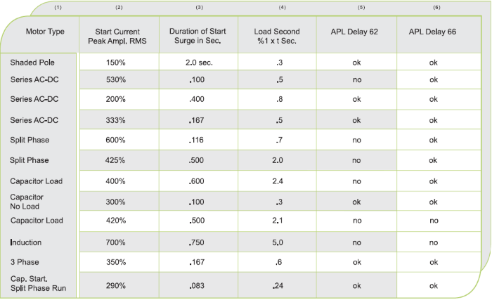
The chart to the right offers some general values. Single-phase induction motors are considered the worst, with a starting winding that can draw 7 or 8 times the running current for most of a second.
Several of the various horsepower ratings witnessed a 750-millisecond surge duration. Induction motors are usually protected by a thermal device contained within the motor. Most protectors that can control the starting surge will fail to trip out on lower overloads. However, this is to prevent damage to the motor. Here, the power wiring is being protected, unlike the device.
Source: Sensata Technologies, Inc.
Switching Power Supplies and Inrush Protection
Switching power supplies (switchers) have features different from those of the familiar linear types. In contrast to linear-type power supplies, switchers are smaller, lighter, and more efficient. They can tolerate an expanded range of input voltage and frequency compared to the linear types. Conversely, switchers cannot recover in the same amount of time; taking longer, they have slightly greater ripple content and a reduced regulation factor than linear.
Switchers also necessitate a minimum load current of 20 to 25 percent for proper functionality. In contrast, linear supplies have been developed to run across various load scenarios – from no load to full load. The peak value of current at turn-on of linear supplies ranges between 10 to 20 times RMS-rated load values contingent on the type of input transformer used. For the most part, and usually without exception, switchers do not use an input transformer but correct the source power directly. This can cause a peak turn-on current of more than 40, even up to 100 times the rated RMS value of current.
Therefore, most switchers incorporate some circuitry in series with the input line to curb this high peak current value. Most smaller units, up to 350 watts, incorporate a thermistor with an initial high cold resistance, which, when hot, decreases quickly to generate an extremely low resistance. This sufficiently limits the cold turn-on peak current. However, if the circuit is turned off and turned back on while the thermistor is in its low resistance phase, the limiting characteristic is considerably less and can permit a high peak current that may lead to nuisance tripping if the rating of the circuit protector is too low.
Larger wattage supplies employ a resistor coupled with a triac or another “soft start” to restrict the initial high-inrush current, typically 20 times the supply's rated RMS value. Though this inrush is rather high, its duration is relatively short, typically from 3 to 5 cycles of 60 Hz or 50 to 80 milliseconds, and in a decaying amplitude. This high-value current is destructive to on-off switches with contacts not designed to resist these stresses.
The steady-state input current of switchers is a train of pulses rather than a sinusoidal wave. Each of these pulses is two to four milliseconds long on 60 Hz power, with peak values two to three times greater than the RMS value of the input current. This high-peak pulse train provokes the delay tube core of magnetic circuit protectors. If the current rating of the protector selected is in a similar range to the rated input current of the power supply, it can lead to a buzzing sound or nuisance tripping.
One of the main characteristics found in most switchers is the inclusion of fold-back circuitry that closes off or limits the pulse width modulator in the likelihood of an overload in an output circuit. This feature protects against overloads on the output and allows the circuit protector to protect the input circuitry.
Selecting a protector two to three times more than the rated input current with a high pulse tolerance delay eliminates the possibility of nuisance tripping, mitigates potential faults, and incorporates an on/off switch with appropriate contacts, all in one component.
If the circuit protector features a load in addition to the switcher, the total load current and waveform must be considered when sizing the protector. Since switchers' inrush currents are usually 50 to 80 ms in duration and have a decaying pattern, the switcher can be best protected with a rapid delay with high pulse tolerance. Selecting a protector less than two times the rated load may produce buzzing or cause nuisance tripping.
Measuring and Managing Inrush Currents
The inrush current must be measured with precision to adequately protect and tailor delays to prevent nuisance tripping. Because the duration of inrush currents may be measured in milliseconds, standard current meters do not offer the necessary speed of response, so an oscilloscope is required. Oscilloscope current probes will saturate and distort waveforms above a value 12 to 14 times the rated currents, giving the impression of a much lower value than the actual.
It is recommended that a current meter shunt be inserted into the main circuit, and the voltage drop across the shunt should be evaluated using a calibrated scope. This offers a clear visual readout of the time duration amplitude and wave shape of the turn-on currents.
Engineers should also conduct a repeated turn-on, turn-off routine. This will help check if the breaker selected can prevent or avoid nuisance tripping. Moreover, the exercise should be performed using the highest line voltage anticipated in the circuit. Pulse-tolerant protectors must be able to accept the first surge of current without tripping while still ensuring equipment is adequately protected, i.e., maximum equipment protection. This is achieved by either shunting high flux peaks away from the armature or utilizing an inertial device to dampen the armature from short-duration pulses.
Each method necessitates a form of compromise. Shunts distort the trip time curve in 600 to 1200 percent overload, which can lead to unacceptable trip times. Inertial dampers are only effective in the area of the first half-cycle of high overload currents. If the high current continues past the first cycle, the inertia wheel will tend to trip out to supply the necessary protection.
Airpax hydraulic magnetic circuit breakers incorporate an inertial wheel to delay the armature. Their high-inrush construction is designed to handle short-duration, high-amplitude pulses—up to 30 times the rated current for about 4 to 8 milliseconds. This feature impacts only the armature without affecting long-duration, lower-amplitude overloads, such as those encountered during motor starting.
The product datasheets provide a comprehensive overview of inrush pulse tolerance. Airpax breakers are available with a wide range of custom delays and trip time curves to manage inrush currents. Pulse tolerances and the delay curve for each potential configuration are appropriate for each product line.
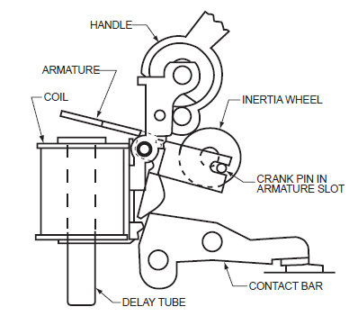
Figure 4. Inertial integration against nuisance tripping. Image Credit: Sensata Technologies, Inc.

This information has been sourced, reviewed and adapted from materials provided by Sensata Technologies, Inc.
For more information on this source, please visit Sensata Technologies, Inc.