Solid State Contactors (SSCs) and Solid State Relays (SSRs) are an ideal match for controlling dynamic loads like motors, particularly where multiple or frequent start/stop cycles are needed in an application. The appropriate choice of a Solid State Relay or Contactor to start and stop a motor with reliability in each application demands an understanding of the requirements placed on the Solid State Control by the application and motor.
Motor control ratings in Horsepower (HP) or Kilowatts (KW) for many Sensata | Crydom Solid State Relays and Contactors simplify the selection process. However, Solid State Relays with General Purpose Ratings can also be used for motor control applications.
This article explains how to choose the right Solid State Relay for motor control when HP or KW ratings are not available.
Note: While Solid State Relays (SSRs) and Solid State Contactors (SSCs) serve similar functions, they are not identical. The key distinction is that a "contactor" must carry a motor control rating in HP or KW. A Solid State Relay with a General Purpose rating may or may not include a motor control rating. Despite differences in labeling, there are no functional differences between a Solid State Relay with an HP motor rating and one without, apart from the evaluation and approved ratings coordination.
Full Load Current (FLA) and Locked Rotor Current (LRA)
When an HP rating for the Solid State Relay is not available, it is crucial to match the control and operating voltages to your application. Additionally, the next most important factor to consider is the initial inrush current that the motor draws during startup.
When a motor starts from a stationary position, it draws a high initial current, known as the inrush current, to overcome the combined inertia of the motor and load. The greater the inertia of the motor/load system, the longer the duration and higher the magnitude of this starting current.
The load current peaks at the moment of actuation as the motor begins from a standstill, limited only by the motor’s winding resistance. This high current, referred to as Locked Rotor Current (LRA), occurs while the rotor or shaft is effectively "locked" and unable to turn. This condition is temporary and can last from a few cycles to several seconds, depending on the mechanical load and application requirements.
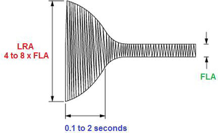
Figure 1. Image Credit: Sensata Technologies, Inc.
As the motor accelerates and reaches its operational speed, the current decreases to a level proportional to the horsepower being delivered to the load. The maximum current drawn in this steady state is known as the motor's Full Load Current (FLA).
The Full Load Current (FLA) and Locked Rotor Current (LRA) relationship vary depending on the motor, but typically, the LRA is 4 to 8 times the FLA. When determining the motor's steady-state current (FLA), it's important to consider that the starting inrush current (LRA) is significantly higher. This inrush current, though short-lived (lasting from a few hundred milliseconds to over 2 seconds), requires the selected Solid State Relay (SSR) to handle these surge currents repeatedly, depending on the application's start/stop frequency.
Note: Solid-state relays and Contactors do not have a wear-out mechanism, so if appropriately chosen using these criteria, they will have a much longer life expectancy (>25 years in most cases) versus similarly rated mechanical relays or contactors.
Selecting SSRs/SSCs With an HP/KW Rating
Solid State Relays (SSRs) and Solid State Contactors that have been certified by safety agencies or regulatory bodies as "motor controllers" come with motor power ratings in Horsepower (HP). This simplifies the selection process for any application since the HP rating is aligned with both LRA and FLA ratings according to UL or IEC standards.
Consequently, motor-rated SSRs and Solid State Contactors are often preferred because the necessary coordination calculations have already been conducted and verified. More information can be found in the Solid State Relays/Contactors for Motion Control flyer on the Sensata website.
A significant advantage of using a motor control-rated SSR or Solid State Contactor is that it simplifies the agency approval process for the end application. Additionally, the approval process for the motor control, along with the associated costs, is already completed.
Selecting SSRs/SSCs Without an HP/KW Rating
When using a standard SSR without an HP or KW motor rating to control the start/stop of a motor, engineers must consider several factors. These include the motor's nominal current value (FLA), inrush current value (LRA), and motor power factor (typically ranging from 0.1 to 0.9). These factors help determine the appropriate turn-on switching type (zero-crossing or random) and whether SSR transient protection is needed.
To aid in selecting the right SSR, Table 1 below offers a straightforward and reasonably accurate rule-of-thumb method to align HP/KW ratings, FLA current ratings, phases, and load voltage.
The load current values in Table 1 are typical, reflecting industry average worst-case motor ratings, with motor efficiency ranging from 20 % for small motors to 60 % for larger motors.
Note that the load current values in the table represent the FLA run currents of the motor and do not account for the start-up surge currents (LRA). However, as mentioned earlier, FLA and LRA are coordinated with HP ratings according to standards.
Table 1. Relationship of HP/KW to FLA, phases and load voltage. Source: Sensata Technologies, Inc.
| Full Load Amperes (FLA) |
| Motor Power |
Single Phase |
Three-phase |
| HP |
KW |
115 V |
230 V |
400 V |
440 V |
115 V |
230 V |
400 V |
440 V |
550 V |
| 1/6 |
0.12 |
4 |
2 |
- |
- |
- |
- |
- |
- |
- |
| 1/4 |
0.18 |
5.2 |
2.5 |
- |
- |
- |
- |
- |
- |
- |
| 1/3 |
0.25 |
6.5 |
3.2 |
2 |
1.8 |
- |
- |
- |
- |
- |
| 1/2 |
0.37 |
8 |
4.2 |
2.7 |
2.4 |
4 |
1.9 |
1.1 |
1 |
0.8 |
| 3/4 |
0.55 |
11.8 |
5.5 |
3.5 |
3.2 |
5.5 |
2.8 |
1.6 |
1.5 |
1 |
| 1 |
0.75 |
14 |
7 |
4.3 |
3.9 |
7 |
3.5 |
2.1 |
1.9 |
1.4 |
| 1 1/2 |
1.1 |
19 |
9.2 |
5.5 |
5 |
10.5 |
5.1 |
2.8 |
2.6 |
2 |
| 2 |
1.5 |
24 |
12.5 |
6.8 |
6.2 |
14 |
6.6 |
3.7 |
3.4 |
2.6 |
| 3 |
2.2 |
35 |
17 |
10 |
9 |
19 |
9.5 |
5 |
4.6 |
4 |
| 4 |
3 |
47 |
23 |
13 |
12 |
25 |
12.7 |
6.8 |
6.2 |
5.5 |
| 5 1/2 |
4 |
61 |
30 |
17 |
15.5 |
33 |
16.5 |
8.9 |
8.1 |
7 |
| 7 1/2 |
5.5 |
80 |
40 |
23 |
21 |
44 |
22 |
12 |
11 |
9 |
| 10 |
7.5 |
- |
48 |
29 |
26 |
56 |
28 |
15 |
14 |
11 |
| 15 |
11 |
- |
64 |
36 |
33 |
- |
41 |
22 |
20 |
17 |
| 20 |
15 |
- |
- |
46 |
42 |
- |
- |
28 |
26 |
21 |
For further assistance in the Solid State Relay choosing process, Table 2 offers General Use ratings versus Typical SSR motor rating (FLA).
The Locked rotor value provided in Table 2 is the real measure of the Solid State Relay surge ability, as this is the parameter that is tested and needs to comply with UL regulations. (The common procedure for UL testing is for the SSR to survive a test current that is six times the full rating for one second. The test is repeated 50 times at a duty cycle of one second on and nine seconds off, with a 0.45 power factor load.)
Table 2. General Use rating current vs FLA/LRA. Source: Sensata Technologies, Inc.
| SSR |
Motor Load Amperes |
| General Use Rating Amperes |
Full Load Amperes FLA (Run) |
Locked Rotor Amperes LRA (Start) |
| 5 |
1 |
6 |
| 10 |
2 |
18 |
| 15 |
3 |
30 |
| 20 |
4 |
36 |
| 25 |
6 |
42 |
| 30 |
7 |
54 |
| 40 |
9 |
72 |
| 50 |
12 |
90 |
| 75 |
17 |
120 |
| 90 |
20 |
138 |
| 100 |
25 |
156 |
| 125 |
30 |
180 |
Note: Table 2 represents all UL-approved Sensata | Crydom SSRs and SSCs. The performance of competitive products may not be similar and may not comply with this “General use vs FLA/LRA value” conversion as shown.
A last point to consider when choosing the correct Solid State Relay is the Solid State Relay/Solid State Contactor’s turn-on switching type of output. For motor control, a “random turn-on” version is typically given preference (to the exclusion of some motor applications with numerically high power factors >0.85) because of the high inductive nature of the load itself.
Zero voltage/zero crossing/zero turn-on (all in reference to the same function) type outputs, which provide significant benefits when controlling resistive loads (with or without a large inrush current), may be not beneficial in situations with very low numerical power factor loads (typically <0.4).
Example Motor Control Use Cases
Example #1
- Application: A Customer is interested in using a Crydom Series1 panel mount SSR (which is not Motor control rated) to start/stop a single-phase AC motor with a rating of 3 HP @ 230 VAC.
- Solution: In Table 1 it is seen that the FLA for a single phase 3 HP motor @ 230 VAC is 17 Amp; in Table 2 it can be discerned that the SSR General Purpose output rating corresponding to a 17 Amp FLA rating is 75 Amp. The conclusion is that the customer can utilize a Crydom D2475- 10 SSR (75 A, 230 VAC, Random turn-on) to control the subject motor.
Example #2
- Application: A Customer is curious about using the Crydom PF Series PCB mount SSR ( is 25A General Purpose rated SSR with no Motor Control rating) to start/stop a three-phase AC motor with a rating of 2.2 KW @ 400 VAC.
- Solution: In Table 1 it can be seen that the FLA for a three phase 2.2 KW motor @ 400 VAC is 5 Amp; in Table 2 it can be seen that the SSR General Purpose output rating corresponding to a 5 Amp FLA is 25 Amp. So, the answer is that yes, the customer will be able to use the Crydom PF series SSR due to it being 25A General Purpose rated.
To conclude, selecting Solid State Relays or Solid State Contactors that carry Motor Control Ratings is simple when the motor load HP or KW ratings are available. However, any Crydom General Purpose rated Solid State Relay can also be applicable through a relatively simple process.

This information has been sourced, reviewed and adapted from materials provided by Sensata Technologies, Inc.
For more information on this source, please visit Sensata Technologies, Inc.