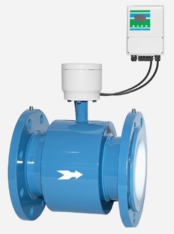
The measurement principle of MFE600E electromagnetic flowmeters is based on Faraday’s law of induction. MFE600E can accurately measure the flow of any electrically conductive liquid, even
those with low conductivities (starting from 5 μS/cm).
Applications
- Water industry: revenue metering, district metering, water abstraction
- Irrigation: Pumping station, pipe line, leakage detection
- Pulp & paper industry: pulp, pastes, sludges and other caustic mediums, liquor, additives, bleaches, colourants
- Metal & mining industry: mediums with a high solid content, like ore or excavator mud

Image Credit: Micro Sensor
Features
- Open flow, no moving components, and no pressure loss in the measurement pipe
- Multiple material choices of electrode and lining, solid against highly corrosive or abrasive medium and applications
- Multiple parameters displayed, including flux, transient flux, velocity, flow %, etc
- Forward flux and reverse flux can be measured
- The variations in fluid density, viscosity, temperature, pressure, and electrical conductivity will not affect accuracy
- EEPROM store parameter settings and cumulative values when power off, supports zero drift, self-diagnosis and alarm functions
- With integrated grounding electrode (DN25-DN500), no need of grounding ring
- Remote display available. Flange, sanitary, threaded, clamping type installation optional.

Image Credit: Micro Sensor
Specifications
| . |
. |
| Diameter |
Flange type: DN6~DN1600, ≥DN20 with built-in grounding electrode |
| Sanitary type: DN6~DN50 |
| Threaded type: DN6~DN50 |
| Clamping type: DN10~DN300 |
| Measurement accuracy |
±0.2%FS,±0.5%FS |
| Electrode type |
Standard fixed electrode, antifouling electrode |
| DN6~DN20: a pair of measuring electrodes, no grounding electrodes |
| DN25~DN500: a pair of measuring electrodes and a pair of grounding electrodes |
| ≥DN600: 2 pairs of measuring electrodes and a pair of grounding electrodes |
| Structure type |
Integrated type, separated type (cable length of separated type≤100m) |
| Rated pressure |
GB: PN2.5, PN6, PN16, PN25, PN40, PN63, PN100, PN160, PN250 |
| ANSI: CLASS 150, CLASS 300, CLASS 600, CLASS 900 |
| DIN: PN10, PN16, PN25, PN40, PN63 |
| JIS: 5K,10K,16K, 20K, 30K, 40K, 63K |
| Others: customizable |
| Electrode material |
316L, Ti, HB/HC, Ta, WC, Pt |
| Lining material |
Neoprene (CR), Natural Rubber (NR), Polyurethane Rubber (PU) |
| Polytetrafluoroethylene (PTFE), F46, PFA |
| Measured pipe |
Stainless steel |
| Flange/body flange |
Carbon steel (standard), stainless steel (optional) |
| Converter housing |
Aluminum die-casting |
| Power supply |
100 V AC~240V AC |
| 12V DC, 24V DC |
| Battery supply (LCD display, RS485 output, wireless output, frequency/pulse output, and the frequency/pulse output is used only for calibration or calibration purposes.) |
| Solar power with storage battery |
| Output signal |
4mA~20mA DC (load resistance 0Ω~750Ω, active output) |
| Hart |
| Frequency, pulse output (Passive, active output optional) |
| Upper and lower limit alarm output |
| RS485 (standard Modbus protocol), RS232 |
| Profibus-DP, Profibus-PA |
| 2G, 4G, NB, LoRa wireless transmission |
| Electrical connection |
M20×1.5 |
| IP protection |
IP65, IP68 (separated type only) |
| Environmental temp. |
-20 ℃ ~60 ℃ |
| Storage temp. |
-40 ℃ ~60 ℃ |
| Relative humidity |
5%~90% |
Working Principle
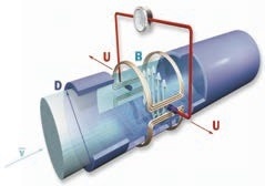
Based on Faraday’s Law of Electromagnetic Induction, the Electromagnetic Flowmeter’s operation produces an induced electromotive force in the liquid conductor as the conductive liquid flows through it.
This electromotive force is directly proportional to the liquid’s velocity, the magnetic flux density, and the conductor’s width (interior diameter of the flowmeter). A pair of electrodes on the flowmeter’s tube wall detect this generated electromotive force, which has the following equation for its magnitude:
U = K×B×V×D
U: Induced electromotive force
K: Instrument Constant
B: Magnetic flux density
V: Velocity
D: Interior diameter of measuring pipe

Figure 1. Working principle diagram. Image Credit: Micro Sensor Co., Ltd