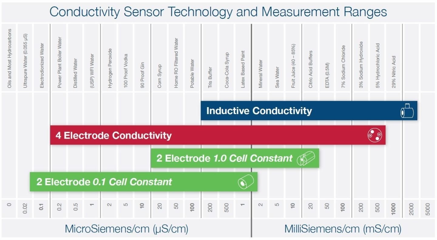
Three primary technologies are employed to measure liquid conductivity, and the choice of sensor technology hinges on the specific application and the expected conductivity measurement range. The chart below offers some illustrative examples.

Image Credit: Hamilton Process Analytics
2 Electrode Conductivity
The 2-electrode (or 2-pole) conductivity sensors are relatively straightforward to comprehend. These sensors consist of two metal plates separated by an insulating material. An AC voltage is applied to these plates, allowing current to pass through the liquid.
The voltage and current are known values, enabling the liquid's resistance calculation. The distance between the electrodes and their surface area must be considered.
These physical dimensions are quantified as a "cell constant." Smaller cell constants, such as 0.1, are optimal for low-conductivity liquids like purified water, while larger cell constants, around 1.0, work effectively for general applications like potable water.
2-electrode sensors have limited range due to the polarization effects of charged ions in the liquid at higher conductivity levels. These sensors are best suited for clean, non-coating liquids and are more susceptible to corrosion and the presence of bubbles.

The Hamilton Conducell UPW Sensor is best suited for applications such as purified water. Image Credit: Hamilton Process Analytics
4 Electrode Conductivity
4-electrode (4-pole) conductivity sensors function similarly to their two-electrode counterparts, but they offer a broader measurement range by incorporating a second pair of electrodes.
This additional pair of electrodes generates a known current, enabling voltage drop measurement across the electrodes. This fluctuating voltage drop compensates for polarization errors encountered in the two-electrode design.
4-electrode conductivity sensors are well-suited for applications where conductivity can exhibit substantial variations. These electrodes are constructed using Titanium and Hastelloy alloys, enhancing compatibility with strong chemicals.
The compensating design provides some capability to rectify issues arising from particulates and bubbles, but it is advisable to avoid using them in liquids prone to heavy build-up.
The installation should consider the exposed electrode design, ensuring that the sensor's tip remains fully exposed to the process liquid, extending by 1 cm in all directions.

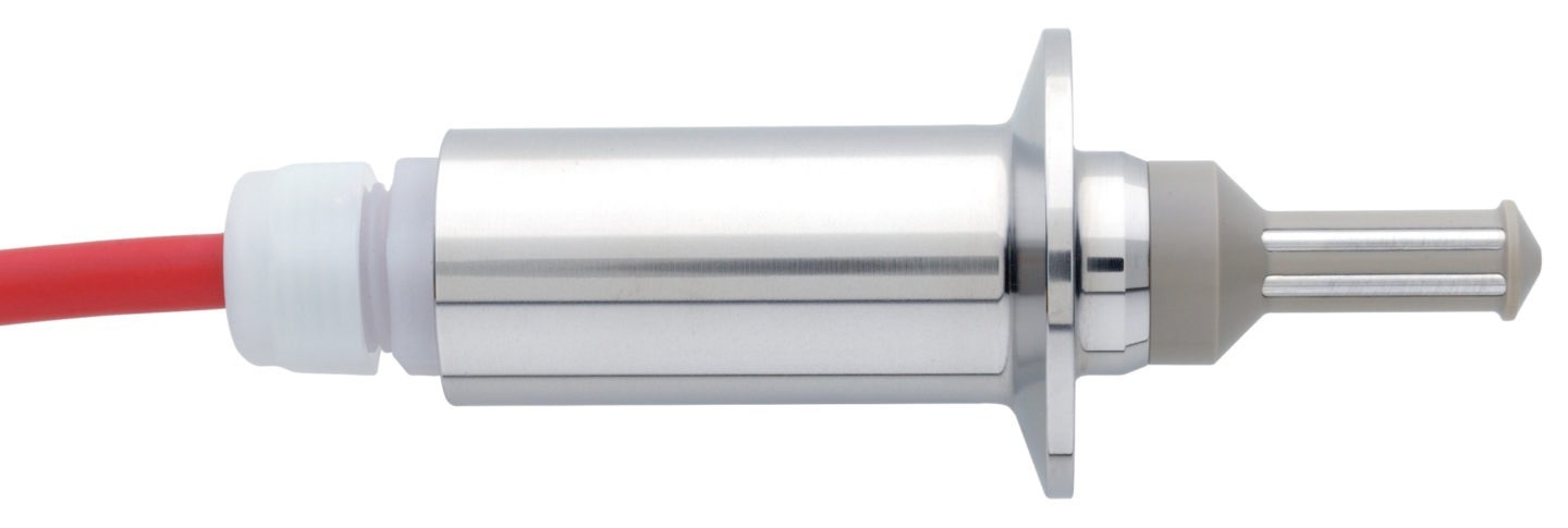
Two of the four electrodes present on the Conducell 4US sensor can be seen in this photo. Image Credit: Hamilton Process Analytics
Inductive Conductivity
Toroidal and electrodeless sensors are commonly referred to as inductive conductivity sensors. Inside the sensor, you will find two insulated magnetic coils, often called toroids. A fixed AC voltage is applied to the primary coil, causing a corresponding current to flow within the surrounding liquid.
The secondary coil responds to this current flow by creating a magnetic field. The strength of this magnetic field is directly linked to the conductivity of the liquid. The magnetic field from the second coil generates its current, which can then be used to measure the liquid's conductivity.
The basic design of inductive conductivity sensors makes them suitable for applications involving coatings and scaling. The non-conductive sensor body is constructed from corrosion-resistant PEEK plastic, which works well with strong acids and bases.
Toroidal sensors, however, are not very sensitive when it comes to accurately measuring low-conductivity liquids like pure water. Their physical size, combined with the electrical field effect, demands sufficient spacing away from the walls of pipes and tanks to prevent measurement errors.

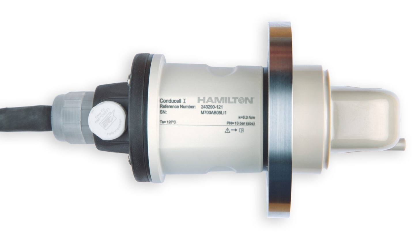
Inductive sensors are well suited for corrosive and coating liquids due to their plastic body. Image Credit: Hamilton Process Analytics

This information has been sourced, reviewed and adapted from materials provided by Hamilton Process Analytics.
For more information on this source, please visit Hamilton Process Analytics.