The Microtrak™ 4 from MTI Instruments is the best laser sensor for measuring displacement, vibration, thickness, height, and more. The Microtrak 4 provides power and data output through a single USB cable. This 1D laser sensor has a linearity of 0.03% FSO and sensor frame rate of 40 kS/sec, and it offers excellent accuracy and speed for even the most complex applications.
The Microtrak™ 4 laser displacement sensor is easy to setup and features a built-in 5 color position indicator that makes it easy to establish the initial gap setup and to monitor rudimentary performance during machine maintenance without referring to an external controller.
Features
The key features of the Microtrak™ 4 laser displacement sensor are as follows:
- No separate power supply required: The sensor uses power supply from your computer's USB port and simultaneously provides all digital output
- Resolution down to 0.03 µm
- Repeatable and accurate measurements from highly reflective to dull surfaces
- CMOS sensor full frame rate of 40,000 per second
- No controller needed: The sensor has a built-in 5-color position indicator that determines nominal laser gap setup and distance placement without using a controller
- Auto gain circuitry automatically determines and controls the ideal laser power required for different types of surfaces
- Configuration/DAQ software and dll included for providing ultimate flexibility in data collection and processing
- Programmable cut-time feature is a bridging function that ignores hole and cut-outs on objects for in process gap control and measurement
- Specular and Glass Models available
- Software compatible with Windows® XP, Vista, Windows® 7 and Window® 8
Industries and Applications for this Product
| INDUSTRY |
MEASUREMENT TYPE |
APPLICATIONS |
| Industrial |
Depth |
DC Motor / Commutator Bar |

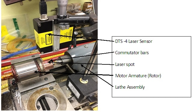
A DC motor armature (rotor) was set up in a lathe to spin it. The MTI laser head, DTS 50-20, has a 20 mm measuring range and 50 mm standoff. The laser was positioned in a FS-3 magnetic mount fixture, pointing at the commutator bars. The lathe was rotated at 180 RPM and the commutator bar run-out was observed on a PC laptop connected to the laser sensor.
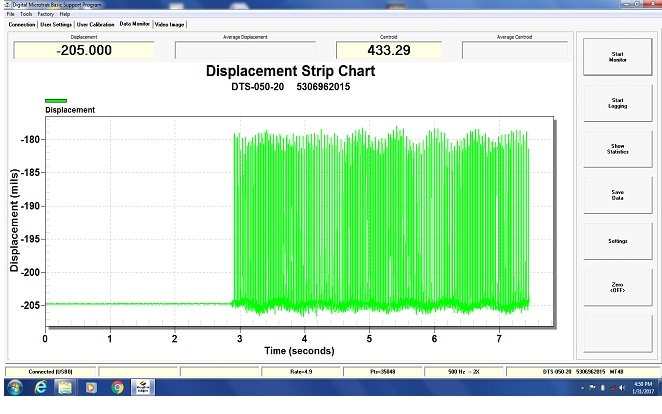
The commutator bar run out was observed using MTI’s MT-4 Basic software. It should be noted that the zoom function should be used to view the bar-to-bar height for a complete revolution. The MT-4 sensor was set to 500 Hz low pass filter, 2000 samples per second.

This is what the commutator bar run out looks like prior to zooming. Nearly 7.5 seconds of data was taken. The gaps between the bars appear as an upward trending spike and the commutator bar gaps can be seen at about 0.020" (0.63 mm) deep.
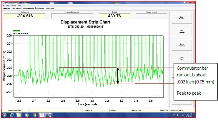
When zooming in on the commutator bar run out, it measures about 0.002" (0.05 mm) p-p run out. The details can be seen in the figure below.


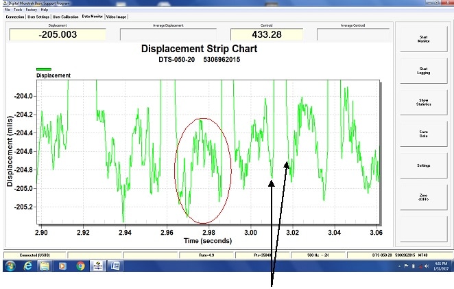
When zooming in closer on an individual commutator bars profile data, a choppy signal is seen. This happens due to a small amount of noise added by the specular nature of the surface and the scratches/texture of the copper surface. This data could be smoothed in a more elaborate program. The big upward spikes, shown in the above image, are gap edges between the commutator bars.