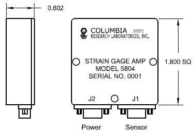
The Columbia Model 5804 Military-Grade Strain Gage Amplifier is used to amplify signals from Columbia’s Full-Bridge Strain Sensors in the DT and DTD Series. The system provides both strain and temperature outputs.
In the case of input offset equivalent strains in that range, the strain output features a microprocessor-driven auto zeroing circuit effective in adjusting for input offsets of up to ±3000 µє equivalent and will instantly drive the output to 0.00 VDC.
This function enables the operator to compensate for any strain offsets caused by gage installation, material fatigue or deformation.
Auto zeroing can be done automatically when the power is turned on, or manually using the auto-zero function pin on the power connection.
A 1000 Ω platinum RTD offers a linearized temperature output of 40 mV / Deg C from -40 °C (0.00 V) to +85 °C (5.00 V). Over its rated operational range, the temperature output will stay within ±3° or ±120 mV of the straight line going through these two locations.
- Strain and Temperature Outputs
- Auto Zeroing Capability
- Wide Input Power Range
- Connects to any Columbia Full Bridge Strain Sensor
Specifications
Operational
Table 1. Source: Columbia Research Laboratories, Inc.
| Operational |
5804 |
| Power Required |
+15 to +35 VDC (+28 VDC Nom.) |
| DC Current Drain |
25 mA Max. |
| Strain Signal Output1 |
±5.000 VDC 0.00 VDC= 0 Micro Strains
Standard: Output corresponding to ±5000 μϵ
Optional: Output corresponding to Specified Range |
| Temperature Output |
0.0 VDC @ -40 °C and 5.00 VDC @ +85 °C ±3° or ±120 mV of straight line passing thru |
| Temperature Scale Factor |
40 Mv/°C Nominal |
| Output Protection |
Over-Voltage and Over-Current Protection on both Strain and Temperature Outputs |
| Measurement Accuracy (Strain) |
±5% |
| Electronic Filtering 2 |
2-Pole Butterworth Filter with response set to -3 dB @2000 Hz |
| Fault Detection |
The amplifier will provide fault detection on all four strain sensor lead wires with a positive indication of any combonation of broken or unconnected strain sensor lead wires. Faults will be indicated by an out-of-range output from the amplifier at the end of the auto-zeroing period. Open fault detection of the temperature probe is intrinsic. |
| Operating Temperature |
-40 to +85 °C |
Physical
Table 2. Source: Columbia Research Laboratories, Inc.
| Physical |
5804 |
| Size |
1.800 ± 0.010" Square x 0.602 ± 0.015" High |
| Mounting |
(3) #6 Clearance Holes |
| Weight |
55 gm Nominal |
| Case Seal |
Epoxy |
| Grounding |
Case Isolated from Signal / Power Ground |
| Power Interface |
Cannon MSN-9PSB Connector |
| Sensor Interface |
Cannon MDM-9SSP Connector |
1 Specify optional Strain Output Range as model number suffix (e.g. Model 5804 - Range ± XXXX μϵ)
2 Optional cutoff Frequencies Available

Image Credit: Columbia Research Laboratories, Inc.
Sensor Pin Functions
Table 3. Source: Columbia Research Laboratories, Inc.
| . |
. |
| 1 |
Bridge Drive (+) |
| 2 |
Bridge Output (+) |
| 3 |
Bridge Output (-) |
| 4 |
Bridge Drive (-) |
| 5 |
Shield/Case Ground |
| 8 |
|
| 9 |
|
Amplifier Pin Functions
Table 4. Source: Columbia Research Laboratories, Inc.
| . |
. |
| 1 |
+DC Power Input |
| 9 |
DC Power Ground |
| 7 |
Strain Output |
| 3 |
Temperature Output |
| 5 |
Signal Ground |
| 4 |
Auto Zero Select |
| 8 |
Shield/Case Ground |