According to Dr Einstein, computers are incredibly fast, accurate, but stupid. Human beings are very slow, inaccurate, yet brilliant. However, the combination of computers and humans is powerful beyond imagination.
However, in contrast to Dr Einstein’s beliefs, present-day machines are not that stupid. They are extremely automated and need very little human interaction to carry out their functions. Thus, design engineers face the challenge of discovering innovative ways to make smart machines smarter.
During operation, the interface contact and fitting of machine components can be affected by various internal and external factors. Each start and stop, input and output, adjustment and readjustment have some kind of impact on the performance of a machine over time.
With their continuous development of more “human-like” features in their machines, design engineers could miss any critical feedback on what these machines are “feeling.”
Every machine has a story to tell, but different machines could be unable to communicate this with their operator. Striving to provide machines with a “voice” could lead to an extremely differentiated, game-changing design.
When all the moving parts that work, run-after-run are considered, interface pressure distribution is very crucial for a machine to carry out its programmed functions.
Pressure mapping technology is a unique tool that enables machine operators, R&D design engineers and field service technicians to capture crucial insights into machine performance.
This ultra-thin sensing technology enables users to get quantitative pressure data, even in implausible spaces. Users can use this data to establish standards for the alignment of the machine, which can then become an embedded feature opening up the communication lines between the machine and its operator.
This page will discuss the fundamentals of pressure mapping technology and its value to machine operators, designers and in-field maintenance personnel. The examples will be supported by real-world machine alignment applications that cover an extensive range of production industries.
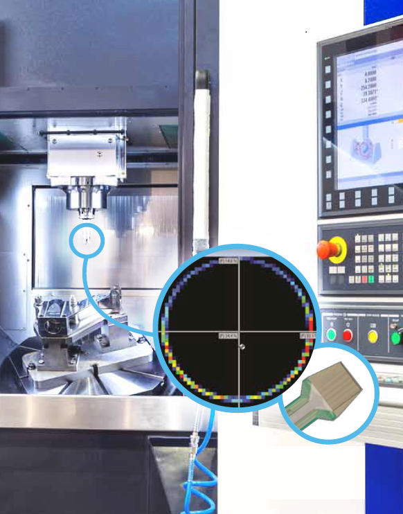
Figure 1. Ultra-thin pressure mapping sensors capture pressure distribution during machine setup. Image Credit: Tekscan, Inc.
What is Pressure Mapping?
It is often the case that interface pressure distribution is not within localized areas of peak pressure, even between relatively flat surfaces. With pressure mapping technology, design engineers can gain insights into areas that might affect design and quality.
There are three main components in pressure mapping systems — scanning electronics, sensors and software — that offer real-time, actionable data that cannot be offered by other techniques in any way.
- The scanning electronics gather analog data from the sensor and transform the data into a digital signal
- The sensor converts compressive pressure loads to a change in resistance
- The software shows the real-time activity of the sensor area, thereby enabling users to observe pressure, force, timing data and contact area
Components of a Pressure Mapping System
Sensor
- High resolution
- Thin and flexible
- Minimal invasiveness

Figure 2. Image Credit: Tekscan, Inc.
Electronics
- Data is instantly relayed to PC through WiFi or USB
- Scan thousands of sensing points inside every sensor

Figure 3. Image Credit: Tekscan, Inc.
Software
- Display pressure data graphs in 2D and 3D
- Pressure distribution data can be displayed in multiple formats for excellent analysis
- Enables video playback of pressure data
- Peak pressures and center of force can be captured in real-time
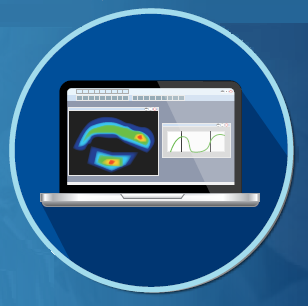
Figure 4. Image Credit: Tekscan, Inc.
There is a Solution for Everyone
All operators are driven by insights. Regardless of the responsibility that operators hold with their company or organization, pressure mapping technology is the key to gaining interface pressure insights to find solutions to crucial design, competitive and technical service requirements. The sections below will offer conceptual and real-world applications to address these requirements.
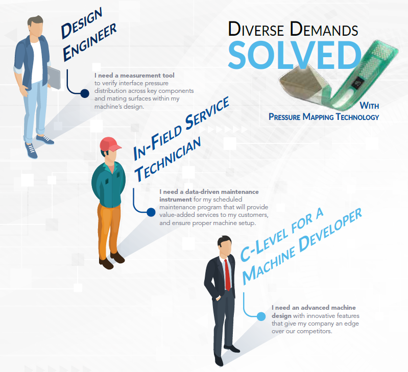
Figure 5. Image Credit: Tekscan, Inc.
Machine Alignment Applications for R&D/Design
Ensuring Repeatability of a Food Packaging Seal
When it comes to food packaging seals, even the slightest defect could prove disastrous, not only to the production company but also to the consumer. In food packaging machine designing, pressure mapping technology enables the capturing of crucial insights to verify the design. This enables the Finite Element Analysis (FEA) model to be enhanced.
Case Example: Controlling Costs of Recyclable Food Packaging
Although product packaging made of renewable or recycled materials offer environmental benefits, their higher up-front costs are the key barrier for several companies. Besides their differing price points, a few of these materials also present flexibility or durability concerns.
A food packaging machine design company incorporated pressure mapping technology into its design process. The company used high-temperature pressure mapping sensors to identify the evenness of the sealing components on the packaging machine and to check whether this pressure distribution would waver over long-time use.
Thanks to this crucial information, the company could optimize the machine for packaging materials with different characteristics, such as paperboard, milk proteins, polyester and others.
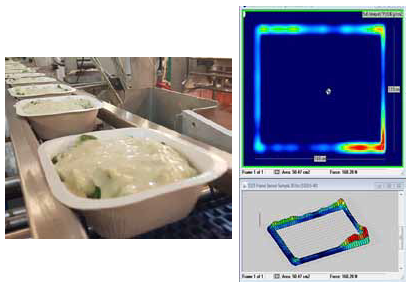
Figure 6. Example of a pressure mapping application for evaluating the seal on a biodegradable food container. Image Credit: Tekscan, Inc.
Other Similar Applications
- Medical supply packaging
- Sealing bar
- Fill line seal
Refining Mold Manufacturing Processes
Pressure mapping technology helps gain a crucial understanding of pressure exchanges and contacts in hard-to-reach spaces. Repeatability and consistency are highly significant in manufacturing operations, and this technology can collect vital data during such operations to help engineers set the baseline metrics for accurate machine alignment.
Case Example: Quality Control of Composite Material Molding
When it comes to the future of aircraft design, composite materials have always and will continue to be, crucial. Composite materials, similar to ceramic and carbon-fiber compounds, provides the advantages of being lightweight, rugged and resistive to corrosive or high-temperature environments. However, they can be costly to manufacture on a large scale, which makes a sound, reliable manufacturing process crucial for ROI.
A commercial airline manufacturer who designs a carbon-fiber-based airplane wing intended to test the and repeatability uniformity of their autoclave molding machines. Their application needed a sensing technology that could be apt for the mold contours, without blocking the molding compartments themselves.
High-temperature pressure mapping systems were found to be an efficient technique for the design engineers to identify the pressure exchanges and contacts in real-time. The thin sensors positioned between a reinforced layer of the mold and the composite materials could then record the variations and determine any potential weak spots in the process.
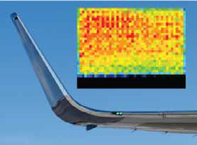
Figure 7. This image depicts an example pressure mapping reading from a composite molding application. In this test, there are clear areas of uneven pressure distribution, indicated by the red spots seen toward the upper-left portion of the testing area. Image Credit: Tekscan, Inc.
Other Similar Applications
- CNC machine design
- Injection molding machines
- Door/window seal quality control
- Robotic welding and other assembly
In-Field Machine Setup and Maintenance Applications
Confirming Interface or Component Uniformity
Pressure mapping technology offers field service personnel an intuitive technique to improve the service they deliver to their customers.
Certain machines need a guess-and-check approach to identify whether adjustments are generating the expected results. Based on whether multiple test runs may be needed, this can be laborious and wasteful. Pressure mapping streamlines these efforts with measurable data.
Case Example: Textile Production Assurance with the NPAT™ System
Textile companies use some of the largest nip machines in the world, for example, the one depicted in Figure 8. Accurate nip contact is critical for preserving the uniformity of the dye applied to the material. Upon identifying improper contact, users should stop all operations, bleach the fabric and re-run the material through the machine.
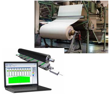
Figure 8. Real-time feedback from the NPAT to be left on the roller while a technician can see the impact of adjustments without having to re-enter the hazard area. Image Credit: Tekscan, Inc.
A textile machine company took major efforts to make sure that their service technicians could detect nip roll uniformity easily and conveniently. They gave their technicians a Nip Pressure Alignment Tool (NPAT) system. The NPAT includes an array of sensing points to detect nip roll uniformity across the length of a nip roll (up to 10,000 mm, or 396 in.) in real-time.
The NPAT software enables the technicians to program a “gold standard” nip roll setting, which can be used to benchmark against other units of the same model machine. This digital quality control tool replaces the nip impression paper, which can only display evidence of peak pressure but not the instant effect of an adjustment.
Other Similar Applications
- Product labeling
- High-volume printing
- Laminating
- Carpet manufacturing
Troubleshooting Production Processes
Pressure mapping can be very useful for production personnel throughout the production journey, right from assembly to completion. Similar to any production facility, delicate materials usually go through various impacts while proceeding through the assembly. The use of pressure mapping technology for routine maintenance and machine setup can help detect potential problem areas in a process.
Case Example: Enhancing Spot-Checking Efforts in High-Throughput Operations
For production managers and engineers, it is a huge challenge to reduce damage and loss in a high-throughput fill line operation. Visual inspection of containers and bottles for damages or scuffs can only help identify that there is a problem somewhere in the process. However, it may be physically unviable to identify where in the process the impact has happened.
Ultra-thin pressure mapping sensor technology is a versatile method that helps improve quality control checkups in fill lines, for example, the machine depicted in Figure 9. Positioning sensors along conveyors or rail lines can detect pressure effects and determine where adjustments could be required.
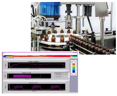
Figure 9. Pressure mapping output of impacts as bottles and containers advance through a fill line operation. Image Credit: Tekscan, Inc.
Moreover, it could be effective to instrument packaging units with sensors and send them through the entire production line to help service technicians identify errors.
Other Similar Applications
- Vibration testing
- Machine commissioning/installation
Integrated Pressure Mapping Solutions
On-the-Fly Spot-Checking Features
Pressure mapping technology can check the effectiveness of a sealing process and improve the packaging design after each run.
When goods and devices are packaged, process consistency is not just vital for enhancing yields; at times, it could literally be the difference between life and death. Pressure mapping helps manufacturers to stay in-tune with their machines, unlike any other technology.
Case Example: Identifying Packaging Defects On-the-Fly
As shown by the previously discussed examples, it is crucial to identify defects in a manufacturing process to keep products fresh, free of damage and sanitary. The integration of pressure mapping technology within the U.I. of a machine can be a quality control measure to help operators keep their products safe and secure.
Bonfiglioli Engineering, a pharmaceutical packaging machine manufacturer, used a software API to integrate pressure mapping technology into a novel blister pack testing machine.
The machine was fitted with a pressure mapping sensor integrated within its lid, as illustrated in Figure 10. When the lid is closed and a blister pack is in place, the machine forms a vacuum across the chamber. If the seal on the blister pack is adequate, each pocket on the blister pack will expand in the vacuum, which the pressure mapping sensor detects.
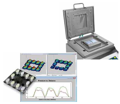
Figure 10. The Bonfiglioli pill pack machine includes a pressure mapping feature that identifies leaks in pill packs. Image Credit: Tekscan, Inc.
In the case of a leak, the air gets sucked out of the pocket, and the pressure mapping output shows the concave cavities, for example, the “improper seal” output depicted on the right. This vital information enables operators to streamline their quality control inspections.
Other Similar Applications
- Injection molding
- Ultrasonic welding machines
- Any form, fill or sealing application
Quantifying Robotic Performance
Machine configuration and alignment are crucially significant if movements and actions of the machine can pose a threat to the operator. The addition of pressure mapping technology into a machine could prove valuable to monitor machine performance and maintain a safe working environment.
Case Example: Qualifying the Safety of Collaborative Robots
Collaborative robots, or Cobots, are called so as they are programmed to carry out their functions while, in some manner, collaborating directly with humans. Cobot systems are developed for an extensive range of applications, and in several cases, they are set up in a production line that lacks a safety caging.
A Cobot system manufacturer recently integrated pressure mapping technology into a new design to quantify the amount of force applied by its arm across various movements. The ultra-thin pressure mapping sensors were set up on the grippers of the robot to detect the pressure distribution when it handled objects.
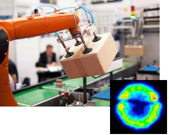
Figure 11. Pressure mapping helps to measure the pressure distribution across the contact area of a Cobot arm while it is in use. Image Credit: Tekscan, Inc.
Thanks to this real-time information, operators can be confident that the Cobot design was working within its optimal baseline metrics, or be warned if maintenance is required.
Other Similar Applications
- Drone delivery
- Pick and place assemblies
- Automated package stacking assembly systems
- Robotic welding and other assemblies
Conclusion
Tekscan Helps Customers Start a Productive Conversation with Their Machine
The successes and examples shared here are the result of an R&D team collaborating with a trusted pressure mapping resource that could offer a solution to fulfill their particular goals. Every process is different, but there are some crucial qualities that should be considered by an R&D team while choosing a collaborative partner:
- Experience and longevity: Is the company reputed in its market and has a proven track record of success?
- Mastery of the technology: Does the company continuously deliver new innovations and optimizations to their technology?
- Proven and diverse application portfolio: Did the company demonstrate various examples in which they were presented with unique challenges and created value-added solutions?